Model 2400 Patch Clamp Amplifier

Price: $4,640.00 
Buy It For Life logo


LOW NOISE, FULL-FEATURED

Designed for voltage clamping using patch electrodes on single channels or whole cells.

A-M Systems Model 2400

Full Function

Whole Cell Clamp or
Single Channel

True Current Clamp

100% Stable
200 kHz Bandwidth

Full Telegraphs

Facilitate Computer
Logging of Settings

The Model 2400 is a low-noise, full-featured patch clamp amplifier designed for voltage clamping using patch electrodes on single channels or whole cells. Its design also allows fast intracellular current clamp measurements with sharp electrodes.

Full-Function Patch Clamp Amplifier for both whole cells and patches
True Current Clamp is 100% stable with bandwidth of 200 kHz.
Switchable Dual Resistive Feedback Headstage
Capacity, series resistance, and whole cell compensation
4-pole Low-Pass Bessel Filters

Internally generated test signals
Telegraph outputs for all major front panel controls
Independent hold, offset, and tracking circuitry
Displays command potentials, cell currents, and voltages

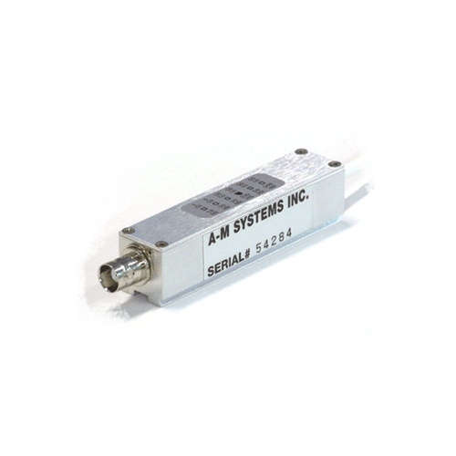
Amplifier current gain can be matched to your experimental needs by selecting one of the three available dual resistive feedback probes, as the gain is partially determined by the value of the resistor in the headstage. There are three heastages to choose from: 1 GΩ/10 MΩ, 10 GΩ/10 MΩ, and 10 GΩ/100 MΩ. The wide range of feedback resistors means currents can be recorded with outputs of 1 mV/nA to 10 mV/fA. The standard probe sent with each unit is the 100 M>Ω/10 G>Ω version, but other values can be selected.

Unlike other patch clamp amplifiers, the Model 2400 has a voltage follower in the probe. This allows this amplifier to be a true fast current clamp amplifier with no instability. An integrated four pole low pass Bessel filter provides flexible signal conditioning. Fine tuning capacity compensation is available to eliminate virtually all electrode-induced transients. Calibrated whole cell compensation provide easy display of membrane capacitance and access resistance.

A host of command potentials are integrated internally within the model 2400, including an automatic tracking command to zero the membrane current, manual controls for offset and holding potentials, and an easily readable digital display. For signals that are more complicated, an external command input with different scaling factors is available for use with any signal source. A digital meter provides accurate values of command signals and membrane currents or voltages, the true RMS noise of the amplifier and experimental setup, the cut off frequency of the low pass filter, and the overall gain of the amplifier plus probe.

Series resistance compensation provides the researcher with the option of introducing either or both predictive and corrective compensation from zero to 100%. Fine and coarse controls for lag provide sensitive control to minimize oscillation produced by compensation close to 100%. Separate compensation controls exist for eliminating transients seen during current clamp experiments when the bridge balance is used.

Telegraph outputs provide analog voltage equivalents of front panel settings including error conditions, amplifier mode and gain, Cmembrane, RMS noise, and low pass filter cut-off value. These telegraphs allow the Model 2400's front panel settings to be automatically recorded by your system software.

The Model 2400 Patch Clamp Amplifier from A-M Systems can serve as a high quality research amplifier in your laboratory, or an inexpensive teaching rig in your graduate courses . Please contact us for information about a free Model 2400 “test drive” in your own lab… No purchase required.
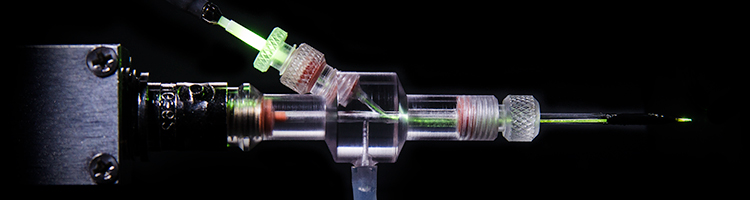
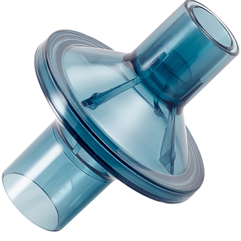
Optopatcher Holders

The Optopatcher provides unmatched accuracy in applying optical stimulation to an in-vivo patch-clamp protocol. The holder houses both an optical fiber and an electrode enabling simultaneous patch-clamp recording and optogenetic activation.

This is a significant advantage in non-slice protocols, such as in-vivo recording from intact animals, whole-cell patch-clamping, LFP recording, and spike/single-unit recording.

The optopatcher was developed by A-M Systems under the guidance of its inventors, Dr. Ilan Lampl and Dr. Yonatan Katz of the Weizmann Institute of Science in Israel. (J Neurosci Meth 214 (2013) 113– 117).

Learn more about Optopatcher holders for optogenetics.

The Model 2400 includes:

  • Operator's manual and Rack mount hardware
  • Model Cell
  • Rack mount hardware

Probe Gain and Bandwidth

Feedback Resistor Probe Gain Maximum Current Minimum Bandwidth
10 MΩ 10 mV/nA 1000 nA 100 kHz
100 MΩ 100 mV/nA 100 nA 100 kHz
1 GΩ 1 mV/pA 10 nA 60 kHz
10 GΩ 10 mV/pA 1 nA 40 kHz

Probe Case Size

  • 2.1" (54mm) long x 0.8"(20mm) high x 1.4"(36mm) wide
  • BNC input connector
  • 1 mm ground pin connector

Maximum Instrument Noise

Voltage clamp modes measured with the internal 4 pole Bessel filter and minimum external noise.

Headstage Resistor (Ωs)
Bandwidth 10 M 100 M 1 G 10 G
1 kHz Theoretical Limit 0.002 nA 0.4 pA 0.1 pA 0.04 pA
1 kHz 0.003 nA 0.5 pA 0.17 pA 0.08 pA

Current clamp modes have noise levels less than 20 µV with inputs shorted.

Internal Bandwidth

For voltage-clamping only the bandwidth is settable from 10 kHz to 100 kHz.

Membrane Current Output Range
Probe Feedback Resistor Output Range
10 MΩ 10 mV/nA-1 V/nA
100 MΩ 100 mV/nA-10 V/nA
1 GΩ 1 mV/pA-100 nV/pA
10 GΩ 10 mV/pA-1 V/pA

Membrane Voltage Output Range

  • 10 mV/mV-1 V/mV

Filter

  • 4 pole Bessel filter with 6 pre-set values, and bypass: 0.5 kHz, 1.0 kHz, 2.0 kHz, 5.0 kHz, 10.0 kHz, and 20.0 kHz.
  • 0.1 kHz resolution

Capacity Compensation

  • Voltage clamp:
    • FAST1: 0-10 pF, 0.2-2 µs
    • FAST2: 0-1 pF, 0.1-10 ms
  • Current clamp
    • FAST1: 0-10 pF
    • No FAST2

Whole Cell Compensation

  • Raccess: 0-100 MΩ
  • Cmembrane: 0-100 pF

Series Resistance

  • RsPre: 0-100%
  • RsComp: 0-100%
  • LagCoarse: 1-100 µs
  • LagFine: 1-10 µs

DC Balance

  • Up to the value of the low feedback resistor in the probe

Hold Command

  • Voltage clamp: ±200 mV
  • Current clamp:
    • Probe Resistor: 10 M / 100 M
    • Command Range: ±200 nA / ±20 nA

Offset Command

  • Voltage clamp: ±100 mV
  • Current clamp: ±1 V

Speed Test Command

  • Used in voltage clamp only.
  • Probe High Gain: 0.2 nA p-p at 60 Hz
  • Probe Low Gain: 1 nA p-p at 60 Hz

Vcomp Command

  • ±5 mV at 60 Hz

Iresist Command

  • ±1 nA at 60 Hz

External Command

  • Voltage clamp: 100 mV/V with the external switch set to divide by 10, 20 mV/V with the external switch set to divide by 50
  • Current clamp:
    • Probe Resistor: 10 MΩ / 100 MΩ
    • /10 Range: ±100 nA/V / ±10 nA/V
    • /50 Range: ±20 nA/V / ±2 nA/V

Patch Clamp Electrophysiology

A-M Systems Model 2400 Patch Clamp Amplifier is compatible with pCLAMP, WinWCP as well as Signal. The following description is for CED's Signal software.

Signal for Windows incorporates many powerful features for whole cell and single channel experiments that make it ideal for electrophysiological recording. Familiar terms, and easily set up protocols for standard requirements enable the user to get started quickly using Signal and a CED Power 1401 data acquisition interface. Signal also incorporates an import function allowing you to analyze data from other recording systems.

Signal can easily all of the stimuli needed, including pre-recorded waveforms to perform voltage and current clamp experiments. In addition, Signal combined with the Power1401-3 data acquisition system are the easiest way to implement Dynamic Clamping in your research protocols.

Multiple sets of stimuli can be stored in one sampling configuration and selected manually or automatically sequenced. Signal can perform on-line measurement of seal and membrane resistance. Leak subtraction and I/V plots can be generated in real time or during offline analysis. Signal also provides mathematical functions to enable complicated curve fitting to waveform data and I/V plots.

Telegraph communication from the A-M Systems Model 2400 Patch Clamp Amplifier allows Signal to set properly scale collected data and send appropriate control voltages to the amplifier for complete control of the recording preparation

Signal can perform complicated curve fitting to your collected measured data, including Exponential, Gaussian, Polynomials, and Sigmoid curve. All data can be plotted and exported in tabular or graphical forms.

WinWCP

WinWCP is a Windows program for recording and analysing signals from whole cell voltage and current clamp experiments.

  • 4-16 analog input channels, 256-8388608 samples/record.
  • Spontaneous event detection.
  • Signal averaging.
  • Command voltage pulse generation.
  • Leak current subtraction.
  • Automatic waveform measurement.
  • Curve fitting with exponential and other functions.
  • Quantal content analysis.
  • Driving function analysis

Control your experimental protocol with automated stimulus generation

  • Generate stimuli on up to 8 DACs and 8 TTL lines.
  • Define as many as 256 sets of up to 500 pulses.
  • Set stimuli at a fixed level or relative to an adjustable holding potential or current.
  • Output multiple sets of arbitrary waveforms per sweep.
  • Sequence through sets of pulses manually, cyclically, randomly or by user-defined protocol.
  • Interactively edit, add and remove stimuli while recording.
  • Define pulses with fixed or stepping amplitudes and durations.
  • Pulse types include square waves, ramp, sinusoid, pulse trains and pre-recorded or user-generated waveforms, for example, recorded action potentials.

Clamp specific sampling support

  • Nominate a particular recording state to be used for seal and membrane resistance measurements.
  • Easy adjustment of holding potentials.
  • Dynamic readout of seal resistance.
  • Membrane analysis option displays measurements of total resistance, access and membrane conductance, capacitive transient decay time constant and membrane capacitance.

Dynamic Clamping

Signal and the Power1401-3 data acquisition system are the easiest way to implement Dynamic Clamping in your research program. Signal includes a fully integrated, easily configurable, high-performance dynamic clamping system. This advanced feature makes the technique readily available to researchers who do not have access to complex customized hardware and software, by providing a professionally designed, maintained and supported package that is usable by all, at a low cost.

In the dynamic clamp technique, a typically nonlinear feedback system delivers current to a cell to represent the actions of virtual ion channels, allowing ion channels or synapses to be simulated or the actions of existing channels to be cancelled.

When used in conjunction with the Power1401-3, Signal can be the bases of your dynamic clamp environment. Standard embedded hardware-based dynamic clamp systems offer feedback that is fast and precisely timed, but these systems are often expensive and sometimes inflexible. PC-based systems, on the other hand, allow more complex feedback, but real-time performance can be poor.

The CED Signal dynamic clamp system gives you the best of both worlds. All real-time aspects of the system are executed by the Power1401's fast embedded processor using pre-calculated lookup tables and optimized floating-point arithmetic, with the feedback calculations triggered by the ADC sampling for maximum stability. This software-based design is quick yet still provides great flexibility. The non-real-time aspects of the system are handled by the controlling PC to allow simplicity and ease of use.

The result: a dynamic clamp system integrated into the standard Signal data acquisition software that outperforms generally available dynamic clamp systems, at a reasonable cost.

System Requirements

Signal Dynamic clamping requires a CED Power1401-3 and a PC with Windows NT 2000, Windows XP, Windows Vista, Windows 7, Windows 8 or Intel Macintosh running Windows. Both 64-bit and 32-bit OS versions are supported. We recommend the computer has a minimum of 2GB of RAM.

The probe is both a current to voltage converter and a voltage follower. The current to voltage converter used in voltage clamping has one of two high value resistors used for amplifying membrane currents. Below is a table of the different probes you can purchase from A-M Systems and their feedback resistors.

Note: For proper operation, the purchase of a Model 2400 Patch Clamp Amplifier Headstage and an electrode holder is required.

Catalog Number Probe Low Gain
Resistor Value (Ωs)
Maximum Current Probe High Gain
Resistor Value (Ωs)
Maximum Current
880210 10M 1000nA 1G 10nA
880218 10M 1000nA 10G 1nA
880222* 100M 100nA 10G 1nA

10G/100M Headstage

* The most commonly ordered headstage is the #880222 10G/100M headstage. A headstage must be ordered at time of instrument purchase.

The input BNC will hold any BNC style electrode holder, and is where any input signal should be connected. The center conductor is connected through a current limiting resistor to a field effect transistor amplifier. Other than the current limiting resistor there is no other protection to the probe so care must be taken to avoid electrostatic discharges. The outer conductor of the BNC is connected to a guard circuit. The guard is a buffered version of the input voltage, so care must be taken not to ground the outer conductor of the BNC.

Cell Simulator Model 2410

The Model 2410 is an electrical equivalent circuit of several types of conditions a research encounters during voltage and current clamping. This model can be used to train students in patch clamp technique, or to improve your patch clamping techniques. It is also very useful to test if your patch clamp is functioning properly without having to worry about connections and pipette problems.

The Model 2410 acts as a "virtual cell" when attached to your amplifier headstage. By selecting one of the offered MODE positions, the internal circuity acts to mimic the condition listed, and present the equivalent electrical signal to your headstage. This enables your students to learn how the recording will vary with the assorted conditions, and what they should look for in their real recordings.

Further, they can learn how the assorted controls on a patch clamp amplifier can affect the recorded signal.

Features of Cell Simulator

  • 7 modes: clogged pipette, pipette in bath, patch seal, two whole cells, inside-out patch, and outside-out patch.
  • Two standard probe inputs: BNC and 2 mm pin
  • 3 independent channels: patch, Na+, and K+ that can be opened/closed manually or by computer
  • Gate switching speeds up to 1 ms
  • Built-in battery recharger
Model 2410 Cell Simulator-110 V, 60 Hz
Model 2410 Cell Simulator-220 V, 50 Hz
Catalog # Product Price
880222 Patch Clamp Headstage-10G/100M Feedback Resistors
Price: $540.00
880218 Patch Clamp Headstage-10G/10M Feedback Resistors
Price: $540.00
880210 Patch Clamp Headstage-1G/10M Feedback Resistors
Price: $540.00
880260 Model Cell
Price: $115.00
688000 Rack Mount Hardware for 3.5" Instruments
Price: $25.00
880010 Model 2410 Cell Simulator-110 V, 60 Hz
Price: $475.00
880015 Model 2410 Cell Simulator-220 V, 50 Hz
Price: $475.00

Requesting a Quote Is Simple

Add your desired products to cart, and choose "Request Quote" as your payment option at checkout.

We will generate a formal quote and email it to you usually in less than 24 hours.

If you have additional requirements, please add them to the Order Notes and click save (as shown in the image).

How to Request a Quote at A-M Systems
 A-M Systems instruments are not approved for use with human subjects in either a clinical or research environment.
 Due to a large volume of domestic and international orders, fulfillment may take as long as six weeks.
Catalog #:880000
Price: $4,640.00
Loading...